

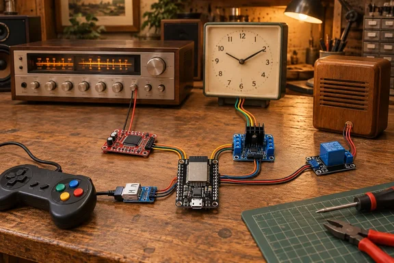
The ESP32 retrofit starts with the old gadget's interface
How-To Geek's argument is easy to follow. ESP32 boards are cheap and come with Wi-Fi and Bluetooth, and hobbyists have published working code that does the hard part. What the roundup skims over is how little the four projects share. One decodes an audio stream. One acts as a USB host. One drives a clock motor through an H-bridge, and one closes a relay across a chime circuit.
Taken together, they show where the real work is in this kind of project. The ESP32 supplies the radio and the processing. The part that decides whether a build succeeds or burns out is the interface layer: an audio decoder, a USB OTG adapter, a motor driver, a relay. A board that suits one project can be wrong for another, and pin assignments copied from one build rarely carry over to a different board.
The sections below follow each build as its author documented it. They separate the author's reported results from How-To Geek's framing and point out where a reader's own hardware might differ.
Grégory Paul's ESP32 Bluetooth receiver needs a VS1053 decoder as well
The first project turns an old stereo or hi-fi receiver into a Bluetooth speaker system. How-To Geek pointed readers to Grégory Paul's ESP32 Bluetooth Audio Receiver, which Paul documents on Hackaday.io. His build uses the ESP32 for Bluetooth A2DP (the Advanced Audio Distribution Profile, the standard for streaming music from a phone) and a separate VS1053 chip to decode the audio. The result lets you stream from a phone to a stereo that has no Bluetooth of its own.
Paul has built more than one version. His first used an Adafruit VS1053 breakout. Later units combined an ESP32-WROOM-32U module with a generic VS1053 MP3 breakout. The parts list is short: an ESP32 module with an external antenna, the VS1053 board, and a headphone jack if the decoder board lacks one. He says fitting an external antenna made the receiver much more reliable and extended its range. That is his experience, and it won't hold for every enclosure or room.
Espressif's own ESP-IDF documentation backs up the basic mechanism. It includes an a2dp_sink_stream example that shows how to receive an A2DP stream and output it over I2S. ESP-IDF files A2DP under its Bluetooth Classic APIs, so if you substitute a different board, check that it supports Bluetooth Classic. The safest choice is to stay with the module family Paul used.
How-To Geek's cost argument is that a $5 ESP32 plus parts should beat any $50 off-the-shelf Bluetooth receiver worth buying. Treat that as an estimate. The ESP32 is only one line on the bill of materials, and the VS1053 board, jack, antenna and power supply all add to it. The better case for building one is that you learn how Bluetooth audio sinks work and end up with a receiver you can repair yourself.
Turning a wired controller into a Bluetooth gamepad takes one of two routes
The controller section covers two different techniques, and they shouldn't be confused. How-To Geek's motivation is durability. The author's original PlayStation 1 and PlayStation 2 pads still work after heavy use, while a first DualSense went back for replacement and several Xbox controllers used on a PC developed stick drift. Which route you take depends on whether your old controller speaks USB.
The bt-gamepad route: a USB controller through an ESP32-S3
For a wired USB controller, How-To Geek recommends Stavros Korokithakis's bt-gamepad project on GitHub. The firmware is written for the ESP32-S3. The S3 acts as a USB host for the wired controller and presents itself to a phone, tablet or PC as a Bluetooth Low Energy (BLE) gamepad. Internally, the firmware parses the controller's HID reports into a standard internal state and then generates BLE HID gamepad reports from that state.
The documented hardware is a Seeed Studio XIAO ESP32S3, a wired USB HID gamepad, and a USB-C OTG adapter (USB-C male to USB-A female) or a powered USB hub. The README includes a power warning: some controllers draw more current than the XIAO can comfortably supply. If yours doesn't enumerate or keeps resetting, put a powered hub in between.
Flashing is done through PlatformIO:
- Connect the XIAO ESP32S3 to your computer over USB-C.
- Build with
pio run -e seeed_xiao_esp32s3. - Flash with
pio run -e seeed_xiao_esp32s3 -t upload. The project uses a custompartitions_4MB.csvpartition table referenced inplatformio.ini. - For normal use, plug the controller into the XIAO's USB-C port through the OTG adapter or powered hub.
- Pair the device from Windows or another host's Bluetooth settings, as you would any Bluetooth controller.
There's also a development environment, seeed_xiao_esp32s3_dev, which turns USB host off and keeps USB serial on for quick flashing and monitoring. With USB host enabled, debug logs go to a hardware UART on GPIO12 (TX) and GPIO13 (RX), and you'll need a 3.3 V UART adapter to read them.
The README also warns about button layouts. USB HID gamepads don't agree on which physical button is "Button 1," and operating systems often rely on per-device mapping databases to sort that out. Because the firmware exposes a generic BLE gamepad, a controller with unusual button ordering may need its mapping changed in src/hid_parser.cpp. The debug log shows which internal bit toggles on each press, which makes that easier. The project describes its mapping in terms of Linux button codes, so Windows users should expect to check button assignments in their games. That last point is our inference; the project doesn't document Windows behaviour.
The Intellivision route: GPIO wiring for a proprietary connector
Colin Vaughn's Intellivision Bluetooth Gamepad Controller works at a lower level. There's no USB involved. The original controller's connector pins are wired to ESP32 GPIOs, and firmware built with lemmingDev's "ESP32 BLE Gamepad" Arduino library advertises the controller over Bluetooth as "Intellivision Controller." The hardware list is an ESP32 development board, an original Intellivision controller, jumper wires, and an optional LiPo battery and charging circuit.
The README gives a full pin map, with ground on the brown wire and controller pins 1–4 and 6–9 mapped to specific GPIOs. It also maps the controls to standard gamepad buttons: the 16-position disc as buttons 1–16, the keypad as 17–28, and the side buttons as 29–31. There's an optional analog mode in which the disc drives the left stick. The project says it is mainly intended for Intellivision emulators. The author also mentions a work-in-progress console dongle that would let the Bluetooth controller work with original hardware.
The README lists current draws of roughly 100 mA in active use and under 1 mA asleep. These are the author's figures, not independent measurements. As How-To Geek notes, even with ready-made software, proprietary connectors mean you'll be soldering or wiring.
A Pragotron PJ 27 slave clock gets NTP time from an ESP32
The clock project is the most specialised of the four, and the one best documented by independent reporting. Oleksii, who writes the smallhacks blog, found an old "slave" clock from 1960 (according to the serial number). It is Pragotron PJ 27, 12V version. Clocks like this usually been used in organizations with central time management systems, e.g. schools, factories, etc. To drive them initially big mechanical "master" clock has been used. The PJ 27 can't keep time by itself. It moves only when a master sends it a pulse.
The signalling is simple but unforgiving. The mechanism expects 1m impulse with different polarity on every run to move the arrows. A plain on/off switch can't reverse polarity, so Oleksii used an H-bridge. Hackaday's write-up of the build describes an ESP32 in combination with an L298N motor controller. The L298N is an H-bridge driver chip, allowing it to easily supply the 12V signals in alternating polarities where required. According to the blog, 12V is wired directly to the L298N controller, 5V L298N output and GND → to the ESP32 5V and GND, and L298N IN1 and IN2 are connected to the GPIO pins 12 and 13. Clocks are connected to the L298N OUT1 motor output.
The software handles timekeeping. As ESP32 does not have real RTC I decided to use NTP over WIFI as a precise time source. This way I can avoid using an additional RTC module with battery. At boot the controller joins Wi-Fi and fetches the time over NTP, and after initial sync time is updated from NTP every 5 minutes. Timezone support is implemented using Timezone. Actual time, slave clock status, wifi status, and NTP sync status is displayed on the OLED screen. The blog says the controller saves the clock's state to ESP32 flash every minute through the Arduino Preferences library, and that the author enlarged the NVS partition to 1 MB. That way the ESP32 knows where the hands are after a power cut.
Setup uses a manual calibration mode. The init mode is enabled by touching GPIO15 and reboot. In this mode, impulses are generated every second. When the slave clock set to 12:00 the pin needs to be released.
The main caution is voltage. There are also 6V, 24V, and 60V versions of these clocks. Commenters on Hacker News pointed out that other makers used different schemes, such as a pulse delivered once per minute advances the minute hand one notch, sometimes with a separate hourly correction signal. Oleksii's wiring is proof that the approach works for one mechanism. Before you connect anything to another clock, check its rated voltage, pulse length and polarity scheme.
The doorbell project keeps the existing chime and adds Home Assistant alerts
The fourth project is the easiest to argue for on cost. How-To Geek's author replaced a basic doorbell with a Ring model that requires a monthly subscription. Without the need for a camera, they would have turned the wired bell into a Home Assistant trigger instead. The guide they cite, on ESP32.co.uk, calls for the bell you already have, a relay to fire the existing chime, and an ESP32. After setup, Home Assistant can send you a notification whenever someone presses the button.
It works like this. The ESP32 detects the button press and reports it to Home Assistant. It then pulses a relay whose contacts are wired across the chime's button input, so the old chime still rings as if the button had been pressed directly. The guide describes an ESPHome build using Home Assistant's native API, with MQTT as an alternative. It also suggests an ESP32-CAM for snapshots, though How-To Geek points out that a camera takes away much of the appeal of reusing the old bell as it is.
The guide makes two recommendations that decide whether the result is dependable. First, add debounce handling for the button. Second, trigger the chime locally on the ESP32 itself, so the bell still rings if Home Assistant or the MQTT broker is down. It also warns that if the doorbell system is fed from mains, you should work only on the low-voltage side of its transformer, follow local regulations, and call an electrician if you're unsure. Treat the guide's pin numbers and relay timing as values for its own example build. Your board, relay and chime set the actual requirements.
What this means for you
Start with the old device, not the ESP32. Identify its interface (line-level audio input, USB HID, proprietary connector, polarity-reversing pulse circuit, or low-voltage chime loop) and then pick the board and interface hardware the matching project specifies. If you're a Windows PC gamer, the controller builds are the most directly useful. A Seeed XIAO ESP32S3 running bt-gamepad pairs like any Bluetooth controller, but check button mappings in your games. The clock and doorbell builds call for more care with electricity than with code.
- Buy the ESP32 variant each project names.
bt-gamepadtargets the ESP32-S3 because it relies on USB host, while Paul's audio receiver uses an ESP32-WROOM-32U with Bluetooth Classic A2DP. - Budget for the parts beyond the microcontroller, such as a VS1053 decoder, OTG adapter or powered hub, L298N driver, or relay, before comparing the cost with a retail Bluetooth receiver.
- If a USB controller won't enumerate or keeps resetting on the XIAO ESP32S3, add a powered hub, as the
bt-gamepadREADME advises. - Check a slave clock's rated voltage and pulse scheme before wiring it. The Pragotron PJ 27 build uses 12 V pulses of alternating polarity, but these clocks also came in 6 V, 24 V and 60 V versions.
- Keep doorbell work on the low-voltage side of the transformer, and have the ESP32 fire the chime locally so the bell still works when Home Assistant is offline.
- Copy pin maps only when you're using the same board as the author, and treat battery and current figures in project READMEs as the author's claims.
Together, these four builds show that an ESP32 can give old hardware a second life for the price of a few parts. They also show the pattern behind every one of them: a working project comes from reading the old device's signals and powering it correctly, and choosing a microcontroller is the easy part. For anyone starting out, the natural next step is the one How-To Geek ends on: learning what separates the ESP32, ESP32-S3 and other variants, because that choice decides which of these projects you can build at all.