

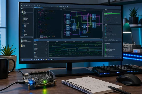
OpenCircuitX arrives as a notable attempt to make FPGA development on Windows feel less like a collection of disconnected command-line utilities and more like a coherent engineering environment, combining VHDL and Verilog editing, circuit visualization, RTL schematic inspection, waveform analysis, and an FPGA build flow inside a single open-source desktop application.
For years, open-source hardware development has offered powerful individual tools but a fragmented user experience. A typical FPGA project might involve one application for writing HDL, another for simulation, a separate waveform viewer, terminal commands for synthesis and place-and-route, and yet another utility for programming a development board.
That workflow can be productive for seasoned engineers. It is also intimidating for students, hobbyists, embedded developers, and Windows users who want to experiment with programmable logic without first becoming experts in build scripts, environment variables, package managers, and vendor-specific project formats.
OpenCircuitX positions itself as a response to that friction. Developed by OpenLabX and released under the permissive MIT License, the project presents an all-in-one electronic design automation environment aimed at digital logic design with VHDL and Verilog.
Its stated focus is not custom-chip production or ASIC tapeout. Instead, OpenCircuitX targets the more accessible and practical world of FPGA development, beginning with Lattice’s iCE40 and ECP5 device families. That distinction matters: these FPGA families have long benefited from mature community-developed toolchains capable of creating configuration bitstreams that run on actual hardware.
For Windows 10 and Windows 11 users, the project is especially interesting because it attempts to put a more approachable graphical layer over a workflow that has traditionally been more comfortable on Linux.
Rather than treating code, schematics, waveforms, and implementation output as isolated stages, the platform brings them together in one working window. That can make hardware development easier to follow because the representation of a design changes as engineers move through the process.
A developer may begin with a VHDL entity or Verilog module, inspect the inferred RTL structure, simulate signals over time, review the final logic mapping, and then build an FPGA bitstream without constantly switching between unrelated tools.
The intended feature set includes:
OpenCircuitX is trying to serve both groups by preserving the HDL-centric nature of FPGA design while making the journey from code to circuit more visible.
When an engineer writes HDL, the goal is generally not to define a sequence of instructions for a CPU to execute. Instead, the source describes digital logic that can be synthesized into registers, multiplexers, arithmetic units, memory interfaces, state machines, and interconnections.
That distinction creates a steep learning curve.
A beginner may write a small block of code expecting it to behave sequentially, only to discover that synthesis infers parallel hardware. An incomplete conditional assignment can infer an unwanted latch. A poorly structured clocked block can create timing or reset problems that do not appear obvious in a text editor.
This is where a visual EDA environment can add real value.
A visual circuit canvas may be even more useful in the classroom or during early prototyping. Students can experiment with gates, counters, LEDs, switches, and registers while seeing the relationship between a graphical circuit and HDL-based implementation.
That does not replace disciplined HDL development. It can, however, make the initial concepts more accessible.
The broader FPGA toolchain typically includes several key stages:
Project IceStorm provides a fully open flow for supported iCE40 parts, while Project Trellis documents the ECP5 architecture and supports open-source bitstream generation through an ecosystem that includes synthesis, place-and-route, device databases, and programming utilities.
For developers, this matters for more than cost.
A Windows-friendly graphical frontend could make these capabilities more available to users who have been reluctant to assemble an open FPGA toolchain manually.
Windows users have often had several choices, none ideal:
A native application does not automatically make FPGA design simple. Hardware development still requires understanding target boards, pin assignments, clock constraints, I/O voltage standards, reset behavior, timing closure, and programming interfaces. But it can remove a layer of avoidable setup complexity.
For now, the Windows version is the central product story.
An FPGA design flow often breaks concentration. An engineer writes RTL in one environment, launches a simulator elsewhere, opens waveform data in another viewer, runs synthesis through a terminal, and inspects results in logs or vendor-specific reports.
Each stage may use different file formats, controls, and assumptions.
A unified workspace can improve the experience in several ways.
For VHDL projects, library management and compilation order are especially important. For Verilog projects, include paths, parameterization, macro definitions, and module resolution can become sources of confusion.
A well-designed editor can surface these issues early rather than leaving the user to discover them only after a long build fails.
The real test will be whether OpenCircuitX handles real projects gracefully:
A canvas can let users create simple combinational and sequential designs visually, observe signal behavior, and build intuition around familiar concepts:
However, the canvas must be designed carefully. A graphical logic tool can become counterproductive if it implies that all hardware designs should be constructed as sprawling gate-level diagrams. Most maintainable FPGA projects are written at RTL, with clear module boundaries, parameterization, reusable components, and automated tests.
The canvas should therefore complement HDL, not compete with it.
They also show why HDL style matters.
For example, a combinational process with incomplete assignments may infer storage behavior. A deeply nested conditional structure may produce a complex priority chain. An arithmetic expression may consume more resources than expected if widths are not constrained carefully.
A good schematic viewer makes these consequences visible.
Still, schematic inspection has limits. Large designs quickly become too complex for a meaningful full-chip diagram. Engineers need filtering, hierarchy navigation, signal search, and the ability to focus on specific modules. Without those capabilities, schematics can become visually impressive but operationally shallow.
A waveform viewer lets designers inspect signals over simulated time. It is where they can see whether a reset occurs on the intended clock edge, whether a counter rolls over correctly, whether a finite-state machine transitions as expected, and whether a data-valid handshake follows protocol rules.
A useful workflow might look like this:
For a unified tool to succeed, its waveform experience must be more than a basic graph. Engineers need useful navigation, hierarchy, timing cursors, signal grouping, radix selection, and clear handling of unknown or high-impedance values. Hardware bugs are often subtle, and a weak waveform interface can make them harder rather than easier to diagnose.
An FPGA is a configurable integrated circuit that can be repeatedly reprogrammed after manufacturing. An ASIC, by contrast, is a custom chip manufactured for a specific design. ASIC development requires a considerably broader and more demanding flow: logic synthesis, static timing analysis, power analysis, physical design, clock-tree synthesis, routing, physical verification, signoff, packaging, testing, and foundry-specific requirements.
The claim that no open-source ASIC flow can support a “real tapeout” is too absolute if interpreted literally. Open-source RTL-to-layout flows have contributed to educational, research, shuttle, and community fabrication efforts, and open process design kits have expanded what can be explored publicly.
But the practical point behind the distinction remains valid.
That is not a criticism of open-source EDA. It is an acknowledgment that ASIC signoff is governed by a different technical and commercial reality.
FPGAs avoid much of that barrier because the silicon is already fabricated. The developer configures a pre-existing programmable fabric rather than sending a brand-new physical design to a foundry.
For OpenCircuitX, that makes the FPGA-only focus practical and credible. The platform does not need to promise to replace the full commercial ASIC ecosystem. It needs to provide a productive route from HDL to functioning FPGA hardware.
Many people encounter digital logic through breadboards, logic-gate simulators, microcontroller projects, or university courses. Moving from those environments into VHDL or Verilog can feel like a leap into an unfamiliar professional toolchain.
OpenCircuitX could soften that transition by unifying visual learning tools with HDL code and FPGA deployment. A learner can begin with a circuit representation, see the equivalent RTL structure, simulate behavior, and then deploy a result to an inexpensive FPGA board.
That progression has real value.
An MIT-licensed application also invites community participation. Developers can inspect the source, adapt the interface to specialized needs, integrate it with educational materials, or extend board support where the underlying FPGA toolchain permits.
The existence of established open-source back ends is encouraging, but integration matters. The platform must accurately pass source files, constraints, target settings, and implementation parameters through each stage.
A polished frontend that hides errors or oversimplifies device configuration would be a serious weakness.
Open-source FPGA flows have traditionally been strongest around Verilog, with VHDL often requiring additional components and more careful compatibility work. VHDL has multiple language revisions, library conventions, package dependencies, and tool-specific behavior that can complicate synthesis and simulation.
Potential users should verify, project by project:
A useful FPGA platform needs clear board definitions that include:
OpenCircuitX will be stronger if it exposes or exports the underlying build commands, preserves human-readable project metadata, and supports repeatable builds outside the GUI. That matters for collaboration, automation, continuous integration, and debugging.
A user should be able to understand what the application is doing—not simply press a button and hope.
Windows has no shortage of proprietary FPGA software. Major vendor suites are capable and widely used, but they can be large, complex, and tightly coupled to specific device ecosystems. Licensing, installation size, supported operating systems, and long-term project portability can all become concerns.
An open-source alternative will not immediately replace vendor tools for every board, every device, or every professional workflow. Nor should it be expected to.
Its value lies in offering a different path:
The project’s emphasis on Windows 10 and Windows 11, along with support for iCE40 and ECP5 FPGA targets, gives it a clear niche. It does not attempt to solve every problem in electronic design automation, and it does not pretend that FPGA development and production ASIC signoff are the same challenge.
That focus is a strength.
If OpenCircuitX delivers dependable builds, useful board support, clear diagnostics, and robust VHDL and Verilog workflows, it could become a valuable entry point for students and hobbyists while remaining useful for open hardware developers who want a cleaner desktop experience. Its greatest contribution may be making the open FPGA stack feel less like a toolbox assembled from separate parts and more like a complete engineering workbench.
 Overview
For years, open-source hardware development has offered powerful individual tools but a fragmented user experience. A typical FPGA project might involve one application for writing HDL, another for simulation, a separate waveform viewer, terminal commands for synthesis and place-and-route, and yet another utility for programming a development board.That workflow can be productive for seasoned engineers. It is also intimidating for students, hobbyists, embedded developers, and Windows users who want to experiment with programmable logic without first becoming experts in build scripts, environment variables, package managers, and vendor-specific project formats.
OpenCircuitX positions itself as a response to that friction. Developed by OpenLabX and released under the permissive MIT License, the project presents an all-in-one electronic design automation environment aimed at digital logic design with VHDL and Verilog.
Its stated focus is not custom-chip production or ASIC tapeout. Instead, OpenCircuitX targets the more accessible and practical world of FPGA development, beginning with Lattice’s iCE40 and ECP5 device families. That distinction matters: these FPGA families have long benefited from mature community-developed toolchains capable of creating configuration bitstreams that run on actual hardware.
For Windows 10 and Windows 11 users, the project is especially interesting because it attempts to put a more approachable graphical layer over a workflow that has traditionally been more comfortable on Linux.
A Unified FPGA Design Environment
The core promise behind OpenCircuitX is straightforward: reduce the distance between an idea, an HDL design, a simulation result, and a programmed FPGA.Rather than treating code, schematics, waveforms, and implementation output as isolated stages, the platform brings them together in one working window. That can make hardware development easier to follow because the representation of a design changes as engineers move through the process.
A developer may begin with a VHDL entity or Verilog module, inspect the inferred RTL structure, simulate signals over time, review the final logic mapping, and then build an FPGA bitstream without constantly switching between unrelated tools.
The intended feature set includes:
- An IDE-style HDL editor for VHDL and Verilog source code
- A visual circuit canvas for graphical logic design and exploration
- An RTL schematic viewer for examining synthesized hardware structure
- A waveform viewer for simulation and debugging
- An integrated FPGA toolchain workflow
- Support for the open FPGA ecosystem surrounding Lattice iCE40 and ECP5 chips
- Native support for 64-bit Windows 10 and Windows 11
OpenCircuitX is trying to serve both groups by preserving the HDL-centric nature of FPGA design while making the journey from code to circuit more visible.
Why VHDL and Verilog Support Matters
VHDL and Verilog remain foundational languages for digital hardware design. They are not conventional software programming languages, even though their syntax can look familiar to programmers coming from C, Python, Java, or Pascal-like languages.When an engineer writes HDL, the goal is generally not to define a sequence of instructions for a CPU to execute. Instead, the source describes digital logic that can be synthesized into registers, multiplexers, arithmetic units, memory interfaces, state machines, and interconnections.
That distinction creates a steep learning curve.
A beginner may write a small block of code expecting it to behave sequentially, only to discover that synthesis infers parallel hardware. An incomplete conditional assignment can infer an unwanted latch. A poorly structured clocked block can create timing or reset problems that do not appear obvious in a text editor.
This is where a visual EDA environment can add real value.
Seeing the Hardware Behind the HDL
An RTL schematic viewer can help engineers answer questions that source code alone does not always make clear:- Did the design infer a flip-flop or a latch?
- Did a
casestatement create the expected multiplexer? - Was a multiplier mapped into dedicated FPGA hardware or generic logic?
- Did optimization remove logic that appeared important in source code?
- Are signals connected as intended between modules?
- Did the synthesis process introduce unexpected resource usage?
A visual circuit canvas may be even more useful in the classroom or during early prototyping. Students can experiment with gates, counters, LEDs, switches, and registers while seeing the relationship between a graphical circuit and HDL-based implementation.
That does not replace disciplined HDL development. It can, however, make the initial concepts more accessible.
The Open-Source FPGA Advantage
OpenCircuitX’s focus on iCE40 and ECP5 devices is strategically sensible. These FPGA families occupy a rare place in the hardware landscape: they are commercially available devices with well-established open-source implementation flows.The broader FPGA toolchain typically includes several key stages:
- HDL elaboration and synthesis
VHDL or Verilog source is analyzed and transformed into a logical representation of the circuit. - Technology mapping
The generic logic is mapped to the resources available inside the target FPGA, including lookup tables, flip-flops, block RAM, DSP blocks, clocking resources, and I/O cells. - Placement and routing
The implementation tools choose physical locations for the logic and determine how signals travel through the FPGA’s programmable routing fabric. - Bitstream generation
The completed design is converted into a configuration file that tells the FPGA how to configure itself. - Programming and validation
The bitstream is loaded into the board or configuration flash, after which engineers test behavior on physical hardware.
Project IceStorm provides a fully open flow for supported iCE40 parts, while Project Trellis documents the ECP5 architecture and supports open-source bitstream generation through an ecosystem that includes synthesis, place-and-route, device databases, and programming utilities.
For developers, this matters for more than cost.
Reproducibility and Transparency
A transparent FPGA flow offers several practical benefits:- Build steps can be scripted and reviewed.
- Projects can be checked into Git without opaque vendor project databases.
- Continuous integration systems can compile hardware designs automatically.
- Developers can inspect the tools that transform HDL into a bitstream.
- Educational users can learn what happens at each implementation stage.
- Long-lived projects may be less dependent on a single vendor GUI or licensing system.
A Windows-friendly graphical frontend could make these capabilities more available to users who have been reluctant to assemble an open FPGA toolchain manually.
Windows Support Is a Major Part of the Story
Windows support should not be treated as a minor checkbox. In the FPGA community, many open-source workflows have historically been easier to install and operate under Linux, where package ecosystems and development tooling are more naturally aligned with command-line engineering software.Windows users have often had several choices, none ideal:
- Use a vendor FPGA suite with proprietary project files and substantial installation requirements.
- Run tools through the Windows Subsystem for Linux.
- Install a collection of ports, packages, and dependencies manually.
- Use a virtual machine or dual-boot setup.
- Avoid the open-source flow entirely.
A native application does not automatically make FPGA design simple. Hardware development still requires understanding target boards, pin assignments, clock constraints, I/O voltage standards, reset behavior, timing closure, and programming interfaces. But it can remove a layer of avoidable setup complexity.
The Importance of a Native Workflow
A polished Windows FPGA environment could be valuable in several situations:- Students using institution-managed Windows PCs
- Makers with inexpensive Lattice-based development boards
- Embedded developers adding FPGA acceleration or custom I/O to a Windows-centric workflow
- Educators building classroom exercises without requiring Linux administration
- Open hardware contributors who want a consistent project experience across machines
For now, the Windows version is the central product story.
From Text Editor to Design Workbench
The most compelling aspect of OpenCircuitX is not that it offers one new synthesis engine or one new HDL dialect. Its potential value comes from integration.An FPGA design flow often breaks concentration. An engineer writes RTL in one environment, launches a simulator elsewhere, opens waveform data in another viewer, runs synthesis through a terminal, and inspects results in logs or vendor-specific reports.
Each stage may use different file formats, controls, and assumptions.
A unified workspace can improve the experience in several ways.
HDL Editing and Project Organization
An IDE-quality HDL editor should help users work with larger projects rather than merely typing source code. At a minimum, practical HDL editing benefits from syntax highlighting, code navigation, error reporting, project file organization, and a clear understanding of module hierarchy.For VHDL projects, library management and compilation order are especially important. For Verilog projects, include paths, parameterization, macro definitions, and module resolution can become sources of confusion.
A well-designed editor can surface these issues early rather than leaving the user to discover them only after a long build fails.
The real test will be whether OpenCircuitX handles real projects gracefully:
- Multiple source directories
- Testbench files separate from synthesizable RTL
- Board-specific constraint files
- External IP blocks
- Parameterized modules
- Mixed project configurations
- Build artifacts that should not be committed to version control
Circuit Canvas and Educational Value
The visual circuit canvas is likely to be one of the platform’s clearest differentiators. HDL can feel abstract because the designer is describing a circuit without drawing it directly.A canvas can let users create simple combinational and sequential designs visually, observe signal behavior, and build intuition around familiar concepts:
- AND, OR, XOR, and NOT gates
- Multiplexers and decoders
- Counters and timers
- Registers and shift registers
- Finite-state machines
- Button debouncing
- LED patterns
- UART transmitters and receivers
However, the canvas must be designed carefully. A graphical logic tool can become counterproductive if it implies that all hardware designs should be constructed as sprawling gate-level diagrams. Most maintainable FPGA projects are written at RTL, with clear module boundaries, parameterization, reusable components, and automated tests.
The canvas should therefore complement HDL, not compete with it.
RTL Schematics and Waveforms: The Debugging Essentials
OpenCircuitX’s inclusion of RTL schematic and waveform viewers reflects two realities of digital design: what the code says and what the hardware does are not always identical in the way newcomers expect.RTL Schematics Expose Synthesis Results
RTL schematics provide a structural picture of the logic inferred by synthesis. They can reveal problems that are difficult to recognize in source form, including accidental latches, unexpectedly wide multiplexers, duplicated logic, missing reset paths, or module connections that do not match the intended hierarchy.They also show why HDL style matters.
For example, a combinational process with incomplete assignments may infer storage behavior. A deeply nested conditional structure may produce a complex priority chain. An arithmetic expression may consume more resources than expected if widths are not constrained carefully.
A good schematic viewer makes these consequences visible.
Still, schematic inspection has limits. Large designs quickly become too complex for a meaningful full-chip diagram. Engineers need filtering, hierarchy navigation, signal search, and the ability to focus on specific modules. Without those capabilities, schematics can become visually impressive but operationally shallow.
Waveforms Remain the Truth During Simulation
Waveforms are the heartbeat of digital verification.A waveform viewer lets designers inspect signals over simulated time. It is where they can see whether a reset occurs on the intended clock edge, whether a counter rolls over correctly, whether a finite-state machine transitions as expected, and whether a data-valid handshake follows protocol rules.
A useful workflow might look like this:
- Write a small HDL module.
- Build a testbench that drives stimulus into the design.
- Run simulation.
- Open the resulting waveform.
- Inspect input and output transitions.
- Identify a failure or unexpected timing relationship.
- Modify the RTL and rerun the test.
- Only then move toward FPGA implementation.
For a unified tool to succeed, its waveform experience must be more than a basic graph. Engineers need useful navigation, hierarchy, timing cursors, signal grouping, radix selection, and clear handling of unknown or high-impedance values. Hardware bugs are often subtle, and a weak waveform interface can make them harder rather than easier to diagnose.
FPGA Scope Is a Strength, Not a Failure
OpenCircuitX explicitly focuses on FPGA design rather than ASIC tapeout. That is a sensible boundary, although the reasoning deserves careful treatment.An FPGA is a configurable integrated circuit that can be repeatedly reprogrammed after manufacturing. An ASIC, by contrast, is a custom chip manufactured for a specific design. ASIC development requires a considerably broader and more demanding flow: logic synthesis, static timing analysis, power analysis, physical design, clock-tree synthesis, routing, physical verification, signoff, packaging, testing, and foundry-specific requirements.
The claim that no open-source ASIC flow can support a “real tapeout” is too absolute if interpreted literally. Open-source RTL-to-layout flows have contributed to educational, research, shuttle, and community fabrication efforts, and open process design kits have expanded what can be explored publicly.
But the practical point behind the distinction remains valid.
Production ASIC Signoff Is a Different Class of Problem
For commercial, high-volume, high-performance ASIC programs, signoff depends on foundry-qualified data, proprietary verification infrastructure, specialized design-rule decks, library characterization, process-specific models, and tightly controlled flows. Major semiconductor companies use deeply integrated commercial toolchains for good reasons: the cost of a missed timing, power, electromigration, manufacturability, or reliability issue can be enormous.That is not a criticism of open-source EDA. It is an acknowledgment that ASIC signoff is governed by a different technical and commercial reality.
FPGAs avoid much of that barrier because the silicon is already fabricated. The developer configures a pre-existing programmable fabric rather than sending a brand-new physical design to a foundry.
For OpenCircuitX, that makes the FPGA-only focus practical and credible. The platform does not need to promise to replace the full commercial ASIC ecosystem. It needs to provide a productive route from HDL to functioning FPGA hardware.
Where OpenCircuitX Could Make the Biggest Difference
The platform’s success will depend less on its headline list of features than on whether it solves persistent pain points in day-to-day FPGA development.Lowering the Entry Barrier
The biggest opportunity is educational.Many people encounter digital logic through breadboards, logic-gate simulators, microcontroller projects, or university courses. Moving from those environments into VHDL or Verilog can feel like a leap into an unfamiliar professional toolchain.
OpenCircuitX could soften that transition by unifying visual learning tools with HDL code and FPGA deployment. A learner can begin with a circuit representation, see the equivalent RTL structure, simulate behavior, and then deploy a result to an inexpensive FPGA board.
That progression has real value.
Supporting Open Hardware Development
Open-source hardware projects benefit from tools that avoid vendor lock-in and proprietary binary project files. A transparent project structure makes it easier for contributors to understand builds, reproduce results, and validate changes.An MIT-licensed application also invites community participation. Developers can inspect the source, adapt the interface to specialized needs, integrate it with educational materials, or extend board support where the underlying FPGA toolchain permits.
Making Small FPGA Projects More Pleasant
Not every FPGA design is a massive professional program. Many are focused, practical, and ideally suited to a lighter workflow:- Custom retrocomputer video logic
- Soft-core CPU experiments
- LED controllers and light engines
- Sensor-interface bridges
- Digital audio processing
- Test equipment
- Keyboard and input adapters
- Serial protocol analyzers
- Hardware acceleration prototypes
- RISC-V learning projects
- Home automation interfaces
Risks, Limitations, and Questions to Watch
OpenCircuitX is promising, but new EDA platforms deserve close scrutiny. Hardware tools are judged not only by interface design but also by correctness, stability, compatibility, and long-term maintenance.New Projects Must Earn Trust
An FPGA bitstream is not merely an export file. It configures real hardware. Errors in the development flow can lead to failed builds, unexpected behavior, timing violations, incorrect pin mapping, or—in poorly constrained designs—electrical problems at the board level.The existence of established open-source back ends is encouraging, but integration matters. The platform must accurately pass source files, constraints, target settings, and implementation parameters through each stage.
A polished frontend that hides errors or oversimplifies device configuration would be a serious weakness.
VHDL Support Requires Particular Care
VHDL support is one of the project’s most important promises, but it is also technically significant.Open-source FPGA flows have traditionally been strongest around Verilog, with VHDL often requiring additional components and more careful compatibility work. VHDL has multiple language revisions, library conventions, package dependencies, and tool-specific behavior that can complicate synthesis and simulation.
Potential users should verify, project by project:
- Supported VHDL language revisions
- Whether VHDL synthesis is fully integrated for the intended FPGA target
- Simulator compatibility
- Support for common libraries and packages
- Handling of generics, records, arrays, and numeric packages
- Behavior for mixed-language projects, if any
- Quality of diagnostics when analysis or synthesis fails
Board Support Is Not the Same as Device Support
Supporting iCE40 and ECP5 devices is valuable, but users ultimately program boards, not abstract FPGA families.A useful FPGA platform needs clear board definitions that include:
- Device part numbers
- Package and pin mappings
- Clock sources
- Voltage and I/O assumptions
- LED, button, UART, SPI, and memory connections
- Programmer configuration
- Constraint templates
- Flash versus SRAM programming options
GUI Convenience Must Not Replace Build Transparency
The best graphical FPGA tools provide convenience without trapping users inside a click-only workflow.OpenCircuitX will be stronger if it exposes or exports the underlying build commands, preserves human-readable project metadata, and supports repeatable builds outside the GUI. That matters for collaboration, automation, continuous integration, and debugging.
A user should be able to understand what the application is doing—not simply press a button and hope.
What This Means for Windows FPGA Users
For the Windows enthusiast community, OpenCircuitX represents a potentially important shift in how accessible open-source FPGA development can become.Windows has no shortage of proprietary FPGA software. Major vendor suites are capable and widely used, but they can be large, complex, and tightly coupled to specific device ecosystems. Licensing, installation size, supported operating systems, and long-term project portability can all become concerns.
An open-source alternative will not immediately replace vendor tools for every board, every device, or every professional workflow. Nor should it be expected to.
Its value lies in offering a different path:
- Open tooling for supported FPGA families
- A Windows-first graphical experience
- VHDL and Verilog development in one workspace
- Visual feedback through schematics and waveforms
- A lower-friction route into practical FPGA experimentation
- A transparent foundation that communities can inspect and improve
The Bottom Line
OpenCircuitX is an ambitious open-source FPGA development platform at a time when the underlying open hardware ecosystem is mature enough to support more user-friendly front ends. Its decision to combine HDL editing, circuit visualization, RTL inspection, waveform debugging, and FPGA implementation is a direct response to the fragmented nature of many open-source EDA workflows.The project’s emphasis on Windows 10 and Windows 11, along with support for iCE40 and ECP5 FPGA targets, gives it a clear niche. It does not attempt to solve every problem in electronic design automation, and it does not pretend that FPGA development and production ASIC signoff are the same challenge.
That focus is a strength.
If OpenCircuitX delivers dependable builds, useful board support, clear diagnostics, and robust VHDL and Verilog workflows, it could become a valuable entry point for students and hobbyists while remaining useful for open hardware developers who want a cleaner desktop experience. Its greatest contribution may be making the open FPGA stack feel less like a toolbox assembled from separate parts and more like a complete engineering workbench.