
The experience described by MakeUseOf author Yadullah Abidi is built around the open-source KiCAD-MCP-Server, a Model Context Protocol bridge that gives an AI client such as Claude access to KiCad’s board and schematic functions. Its advertised examples—placing a resistor and capacitor, laying out an LED matrix, defining an outline, adding mounting holes, assigning net classes and invoking DRC—are broadly consistent with the project’s own tool inventory and recent releases.
What the original account understates is the maturity gap between a successful guided demo and a design workflow that is safe to trust with a board you intend to order. The project has made substantial progress, but its release history documents fixes for schematic corruption, stale project state, disappearing net-class settings, failed deletions and incomplete schematic parsing. That does not make the tool unusable. It means KiCad remains the authority over the design, while Claude is an automation layer operating under supervision.
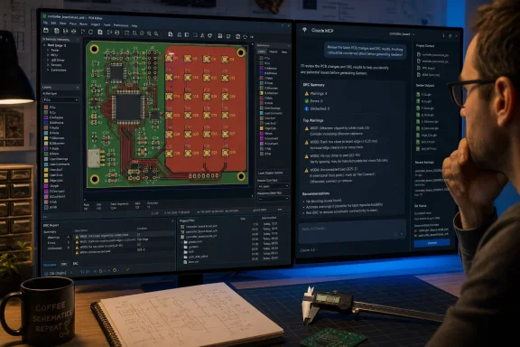 KiCAD-MCP turns prompts into KiCad operations
The useful technical change here is not that Claude suddenly understands electronics. KiCAD-MCP exposes actions that KiCad users already perform through its editors, command-line tools and APIs: creating a board outline, placing a footprint at coordinates, creating tracks, defining a copper zone, inspecting nets, and invoking electrical or design-rule checks.
For a Windows hobbyist or developer, that can remove a surprising amount of mechanical work. A prompt specifying an 100 mm by 80 mm board, rounded corners, four mounting holes offset from the edges, and eight LEDs arranged in a 4-by-2 grid is more reliable than manually repeating placements—provided the prompt contains the dimensions, origin and spacing that KiCad needs. The AI is translating an intent into a sequence of discrete operations; it is not inferring the manufacturing constraints that were omitted.
That distinction matters most when users hear claims that the arrangement “lowers the skill ceiling.” It lowers the entry barrier for operating KiCad and can shorten layout work for experienced users. The skill ceiling is still set by circuit behavior, package selection, return-current paths, impedance requirements, thermal limits, creepage and clearance, EMC, assembly tolerances, and the limits of the board fabricator.
Claude can add a ground pour because the server supplies an action for it. It cannot establish from a vague request whether a split plane will create a bad return path, whether a USB differential pair has the necessary impedance stackup, or whether a switching regulator layout will radiate enough noise to compromise the rest of the board. Those are engineering decisions, not menu-navigation problems.
The project’s own releases show why version control matters
The KiCAD-MCP-Server project has moved fast enough that tutorials and screenshots can describe workflows that no longer match the safest version to use. Its first tagged release, version 2.3.0 in July 2026, included repairs for two KiCad 10 schematic-corruption mechanisms. The project said components created through its schematic tools previously lacked data necessary for correct connectivity and electrical-rule checking in some cases.
That is a serious correction, not a cosmetic polish item. A schematic that appears populated but does not correctly bind pins and wires can lead to an apparently successful workflow with an incomplete netlist. In PCB design, a missing or misidentified connection is the difference between a convenient prototype and a board order that comes back unusable.
Version 2.5.0 also fixed a net-class assignment path that had degraded to a silent no-op on real projects. The failure was especially relevant to the workflow promoted in the MakeUseOf piece: asking Claude to establish power-net rules, clearance values or track widths only helps if those settings are actually persisted in the .kicad_pro project file and survive the next save.
Then version 2.6.0, released in late July, addressed a bug in which deleting an item from a board could break the MCP session. Its release notes also describe a safeguard against an older state-management problem where stale in-memory project data could overwrite custom net-class definitions when a board was saved.
Those fixes are evidence that the project is actively maintained, but they also establish the operational rule users should adopt: treat the MCP server like development software with write access to valuable design files. Use a tagged release rather than blindly following a repository’s current branch, and keep the KiCad project under Git or another versioned backup method before letting an agent make bulk changes.
Live KiCad editing has a synchronization trap
The project uses two broad ways to work with a board. One operates on files through the older pcbnew path; the other uses KiCad 9 or later’s IPC interface for a live connection to the running application. The second mode is appealing because changes can appear in the KiCad UI immediately, rather than requiring a reload.
But live synchronization is also where the project’s most consequential limitation appears. Its documentation explains that the server has to “pin” a project session to one backend. If an agent edits a board through the file-oriented route while KiCad’s GUI holds a different in-memory copy, switching carelessly between the two could overwrite edits or leave the application showing stale information.
The project now prevents some of those transitions specifically to avoid a lost-edits scenario. A board created while the server is operating in file mode remains in that mode until the user reopens the project in KiCad and explicitly reconnects it. That is safer than silently changing backends, but it makes the workflow less seamless than a demo video suggests.
Windows users should plan around that behavior. Start with a copy of the project, decide whether the task is a batch edit or a live GUI session, and avoid editing the same board manually in KiCad while Claude is making file-backed changes. If the board must move into a live session, save it, close or reload it in KiCad, confirm the intended file path, and only then reconnect the agent.
This is ordinary source-control discipline applied to EDA files. It becomes more important when the agent is capable of moving dozens of footprints, changing rules or refilling zones in a single request.
DRC is a gate, not a manufacturing sign-off
KiCad’s own documentation is clear about the role of the Design Rules Checker: it checks whether a PCB meets the rules defined in Board Setup, whether pads are connected as expected, and—when enabled—whether the schematic and PCB are in parity. The KiCad command-line interface can also run PCB DRC and produce a report, which makes it practical for an MCP server to invoke validation after an automated edit.
That is a valuable workflow. It is also narrower than the implication that a clean DRC result proves a board is ready to fabricate.
DRC can detect that a clearance rule was violated, that an unrouted connection remains, or that an existing track conflicts with the board’s configured rules. It cannot validate that the rule values are appropriate for a particular fabricator, voltage, layer stackup or controlled-impedance requirement. It cannot verify that Claude chose the correct pad geometry for a real component, or that the footprint’s pin numbering matches the manufacturer’s datasheet.
The original report acknowledges that Claude can select the wrong footprint. This should be treated as a mandatory review item, not an occasional cleanup task. Before generating Gerbers, users should verify at minimum:
- The manufacturer part number, package drawing and pin-one orientation match the assigned footprint.
- Every power pin, exposed pad, mounting hole and connector pin has the intended net assignment.
- Board-outline dimensions, hole diameters and edge clearances conform to the chosen fabricator’s published capabilities.
- DRC and ERC have been run after zones are refilled, with warnings reviewed rather than simply dismissed.
- Gerber, drill and assembly outputs are inspected in a separate viewer before an order is placed.
For a simple LED board or sensor breakout, this review can be quick. For mains-powered, battery-charging, RF, automotive, medical, aerospace, high-current or high-speed work, an AI-generated starting point is not an engineering sign-off.
Claude Code is not the only client, and that is useful
The MakeUseOf article moves between Claude Code and Claude Desktop configuration, but the important compatibility point is broader: MCP is designed so the server can be connected to clients beyond a single Anthropic application. KiCAD-MCP-Server documents Claude support, while describing itself as compatible with MCP-capable AI assistants.
That gives Windows developers a choice. Claude may be convenient if it is already part of a coding workflow, particularly for embedded projects where firmware, a bill of materials and the PCB layout need to be discussed together. But the board files should remain portable KiCad projects, and the review process should remain usable without the AI client that created the changes.
The strongest use of this setup is therefore neither full autonomous board generation nor conversational replacement of an electrical engineer. It is controlled automation: generate repetitive geometry, inspect a project, explain a DRC report, prepare a first-pass placement, or make a scripted mechanical revision that a human then checks in KiCad.
For Windows users willing to keep backups and review every electrical and mechanical consequence, Claude plus KiCAD-MCP can make KiCad considerably less tedious. For anyone about to send an AI-edited board to fabrication without opening the schematic, footprint properties, board setup and Gerber files themselves, the project’s own bug history supplies the reason to stop first.