

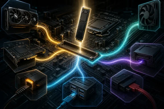
That does not mean every additional NVMe drive will reduce graphics performance or disable ports. The important point is more precise: the consequences are specific to the motherboard model, the particular M.2 slot, the installed CPU, and sometimes a BIOS setting. A row of identical-looking M.2 heatsinks is not a reliable guide to whether the slots are electrically independent.
For Windows PC builders, this matters at upgrade time. A new system drive, game library drive, or scratch SSD can unexpectedly coincide with a graphics slot running at a reduced width, an external-storage port losing capability, or older SATA disks disappearing from Windows because their motherboard ports have been disabled. The remedy is planning from the manual’s lane-sharing notes, not assuming that every advertised socket can operate at full speed simultaneously.
M.2 is a connector, not a promise of dedicated PCIe lanes
It is tempting to describe every M.2 slot as “using PCIe lanes,” but that is too broad. M.2 describes the physical connector and module format. A particular socket may support PCIe/NVMe storage, SATA M.2 storage, or both, depending on the board’s design.
ASUS’s documentation for the TUF Gaming X670E-Plus WiFi illustrates the distinction: its M.2_2 slot supports both PCIe 3.0 x4 and SATA modes. That matters because the resource consequences can differ according to the installed drive and operating mode. A buyer should therefore identify both the SSD protocol and the capabilities of the exact socket before drawing conclusions from an M.2 label alone.
The motherboard manual usually divides storage support into slot-by-slot entries. Those entries reveal the PCIe generation and width, supported CPU families, and whether SATA M.2 is accepted. More importantly, nearby notes often say what the slot shares. Those short footnotes can be more consequential than the headline number of M.2 sockets.
One M.2 drive can split the graphics and expansion connection
The MSI MPG X870E Carbon WiFi is a clear example of an M.2 socket competing for CPU-provided PCIe resources. MSI specifies that its PCI_E1, PCI_E2, and M2_2 connections share bandwidth. Its BIOS guidance describes a configuration that sets PCI_E1 to PCIe 5.0 x8, PCI_E2 to PCIe 5.0 x4, and M2_2 to PCIe 5.0 x4, enabling the secondary expansion slot and M2_2.
This is a lane-allocation decision, not evidence that the board has malfunctioned. The platform has a fixed high-speed connection to distribute. Enabling a x4 M.2 path and a x4 secondary slot leaves x8 for the primary slot in MSI’s documented configuration.
There is also a significant CPU caveat. MSI says M2_2 on this board supports up to PCIe 5.0 x4 with Ryzen 9000- and Ryzen 7000-series processors, but is unavailable with Ryzen 8000-series processors. A motherboard specification alone is thus insufficient: storage planning must include the actual processor installed.
The pattern is not exclusive to AMD AM5 systems. ASUS states that on the ROG Maximus Z890 Apex, enabling M.2_3 makes the primary PCIEX16(G5)_1 slot run at x8. Enabling both M.2_3 and M.2_4 also disables the second PCIEX16(G5)_2 slot. This LGA1851 example reinforces the broader lesson: an M.2 upgrade can be part of the same allocation pool as PCIe expansion, but the exact result is determined by the board.
It would be wrong, however, to turn these examples into a universal rule that installing an extra M.2 SSD always halves graphics connectivity. Other boards place the trade-off elsewhere, and some M.2 slots may not share the primary graphics path at all.
The trade-off may be USB or SATA, not the GPU
MSI’s MAG X870E Tomahawk WiFi demonstrates a different design choice. Its rear 40Gbps USB Type-C ports and M2_2 share a PCIe 5.0 x4 connection. With a device installed in M2_2, both operate at PCIe 5.0 x2. MSI further documents that selecting M2_2 at PCIe 5.0 x4 in BIOS disables those rear USB ports.
For a Windows user, that can be more disruptive than a benchmark figure. Those ports may be the intended connection for a fast external SSD, docking device, or other high-bandwidth peripheral. A new internal drive could leave the PC operating normally until an external device is connected and the missing ports or reduced link become apparent. Anyone relying on rear Type-C connectivity should treat it as a first-class requirement when choosing an M.2 slot.
SATA sharing creates an equally practical problem. ASUS says that when M.2_2 on the TUF Gaming X670E-Plus WiFi runs in PCIe x4 mode, SATA6G_1 and SATA6G_2 are disabled. If a Windows installation, media archive, backup drive, or optical drive is attached to either affected port, it may no longer appear after the M.2 configuration changes.
The immediate troubleshooting temptation is to suspect a failed drive, a loose SATA cable, or a Windows storage-driver issue. The manual’s lane-sharing section should be checked before spending time on those possibilities. On a board with this behavior, moving a SATA cable to an unaffected port or choosing another compatible M.2 slot may be the appropriate fix.
What x8 means—and what it does not prove
A reduced-width primary graphics slot sounds alarming, particularly when the motherboard labels it as an x16-sized slot. Physical slot length and active electrical width are different things. A full-length graphics card can operate with fewer active PCIe lanes when the board’s routing and firmware configuration call for it.
Theoretical bandwidth provides useful context. PCI-SIG figures place PCIe 5.0 x8 at 31.51 GB/s per direction, the same maximum theoretical bandwidth as PCIe 4.0 x16. PCIe 5.0 x16 reaches 63.02 GB/s per direction. In other words, a Gen5 x8 allocation is not equivalent to an older, low-bandwidth x8 arrangement; its theoretical bandwidth matches a full Gen4 x16 link.
That comparison is reassuring context, not a blanket performance guarantee. Gamers Nexus tested an RTX 5090 across 16 scenarios and reported a roughly 1–4% maximum difference between PCIe Gen5 x16 and Gen3 x16 in that particular test suite. The result supports a narrow observation: even a much lower-generation x16 connection showed limited differences in those tested cases.
It does not establish the performance of every graphics card, game, creative application, AI workload, or PCIe configuration. It is also not a direct test of a particular board after enabling a particular M.2 slot. Users with an unusual workload, multiple add-in cards, capture hardware, or professional GPU requirements should not substitute a general benchmark for their own board documentation and workload testing.
Likewise, no general conclusion should be drawn here that an older-generation NVMe drive is always sufficient for gaming. Storage needs depend on the workload, and this evidence does not provide a directly relevant game-loading or DirectStorage comparison.
How to check an M.2 upgrade before buying an SSD
The safest process is simple, though it requires reading beyond the marketing specifications.
- Identify the exact motherboard and CPU. Board revisions, processor families, and supported BIOS options can affect whether a slot is available or at what speed it runs. The MPG X870E Carbon WiFi’s Ryzen 8000-series restriction is an example of why the CPU matters.
- Confirm the SSD type. Determine whether the planned drive is PCIe/NVMe or SATA M.2. Then confirm that the target socket supports that protocol.
- Read the storage and expansion sections together. Look for wording such as “shares bandwidth,” “when populated,” “runs at x8,” “disabled,” or “BIOS configuration.” Do not stop at the M.2 slot count.
- Map existing hardware to ports and slots. Record where the GPU, secondary PCIe cards, SATA drives, and USB-dependent devices are connected. This exposes conflicts before a Windows drive vanishes or a required rear Type-C port is unavailable.
- Decide which capability matters most. A workstation using fast external storage may prioritize rear USB 40Gbps ports. A system with several SATA disks may reserve an M.2 slot that disables no SATA ports. A build requiring multiple PCIe cards may value preserving expansion-slot availability over installing an SSD in the fastest-listed socket.
- Check BIOS guidance before changing hardware. Where the board allows lane allocation, document the current settings and understand the stated result. If Windows storage or peripherals disappear after the change, revisit the board’s sharing rules before assuming a software failure.
Treat the manual as part of the motherboard specification
Modern boards often offer impressive combinations of PCIe 5.0 storage, several M.2 sockets, full-length PCIe slots, high-speed USB, and SATA. But the advertised connectors do not necessarily represent simultaneous, independent high-speed paths. In some configurations they are alternatives drawing from the same underlying resource pool.
That is not inherently a defect. It is an engineering trade-off that lets a board expose flexible connectivity. The problem arises when a builder assumes flexibility means every option is free of consequences.
Before filling that inviting empty M.2 slot, check the exact storage specification, expansion-slot sharing notes, CPU compatibility details, and relevant BIOS documentation. A few minutes spent there can prevent a far more confusing Windows troubleshooting session—and help ensure that the new SSD improves the system without quietly taking away a port or expansion capability that mattered more.