

How the IBM AT and Intel ATX standards gave PSU wires their colors
The timeline is well documented. In IEEE Spectrum's history of computer power supplies, Ken Shirriff writes that in 1984, IBM released a significantly upgraded version of its personal computer, called the IBM Personal Computer AT. Its power supply swiftly became the de facto standard and remained so until 1995, when Intel introduced the ATX form-factor specification, which among other things defined the ATX power supply, still standard today. Archived Intel documents include ATX Specification 1.1 from February 1996 and ATX Specification 2.01 from February 1997.
XDA says ATX kept the AT-era black, red, yellow and blue wires and added orange, purple, green and gray for the new functions. It also points out that the older four-pin Molex drive connector already used yellow for +12 V, red for +5 V and black for ground. ATX built on existing practice instead of starting from scratch.
The XDA account describes AT-era connectors as easy to get wrong. The motherboard power plugs could go in backwards and fry the board, and stiff cables ran to a mains toggle switch on the case that could short if miswired. ATX replaced that with a single keyed main connector and moved power-on control to a low-voltage signal the motherboard manages. That signal is the green wire.
The ATX 24-pin color code, wire by wire
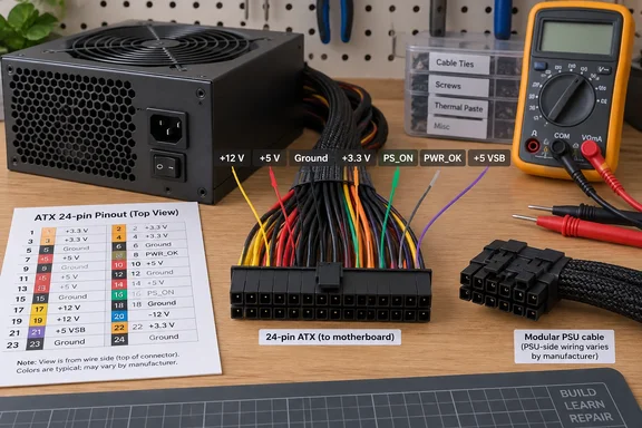
Several pinout references reproduce the colors from Intel's design guides, and they agree on the core mapping. Intel's 1998 ATX power supply design guide lists the same set, including two colors that XDA's shorter list leaves out: white and brown.
| Color | Signal | What it does |
|---|---|---|
| Black | COM (ground) | Common return path, not a voltage rail |
| Orange | +3.3 V DC | Main 3.3 V output |
| Red | +5 V DC | Main 5 V output |
| Yellow | +12 V DC | Main 12 V output |
| Blue | −12 V DC | Legacy negative rail |
| Purple | +5 VSB | Standby power while the PSU is plugged in |
| Green | PS_ON# | Motherboard's "turn on" request |
| Gray | PWR_OK | PSU's "power good" status |
| White | −5 V DC | Legacy rail, optional on newer supplies |
| Brown | +3.3 V sense | Remote voltage sensing, where present |
A 24-pin ATX12V pinout table describes the green wire as Power Supply On (active low). "Active low" means the PSU turns on when the line is pulled to ground, and a reference guide notes that when the line is connected to GND (by the motherboard), the power supply will turned on. It is internally pulled up to +5 V inside the power supply. In normal use, PS_ON# is activated by motherboard when you press and release the computer power button while it is in standby mode.
The gray wire carries the signal the other way. The same pinout table calls PWR_OK a status signal generated by the power supply to notify the computer that the DC operating voltages are within the ranges required for proper computer operation. It remains low for a brief time (100–500 ms) after the PS_ON# signal is pulled low. The idea goes back to the original IBM PC, whose supply, according to IEEE Spectrum, provided a "power good" signal when all four voltages were correct. PWR_OK tells you the PSU's outputs are in range. It says nothing about the health of the rest of the system.
Purple is the standby rail. Instructables' bench-supply guide explains that it always has 5V available, even if the PSU is turned off, as long as it is plugged in to the AC mains. Brown, where present, is a sense line, not a power line. +3.3 V sense should be connected to the +3.3 V on the motherboard or its power connector. This connection allows for remote sensing of the voltage drop in the power supply wiring.
The main connector's size has changed too, while the colors stayed the same. The original ATX systems had 20-pin main connector P1. When PCI Express® bus was introduced, PCIe cards needed up to 75W extra. To provide the additional wattage, the old part has been replaced by a new 24-pin P1.
PC power has changed even though the colors haven't
XDA says the colors haven't changed "because PCs still use the same voltages they did back then" and that "the underlying electronic architecture hasn't changed." That goes too far. The rail names on the connector are much the same, but the way a PC uses them has changed a lot.
The −5 V white wire shows it best. A pinout reference derived from Intel's design guide notes that −5 V is optional on newer ATX-2 supplies, it is for use with older AT class expansion cards and can be omitted on newer units. So a color from the scheme has mostly dropped out of current hardware, and a 1998 reference table may list a wire your PSU doesn't have.
The processor side changed further. IEEE Spectrum notes that computer power systems became more complicated in 1995 with the introduction of the Pentium Pro, a microprocessor that required lower voltage at higher current than an ATX power supply could provide directly. Intel responded with the voltage regulator module (VRM)—a DC-to-DC switching regulator installed next to the processor. That first VRM reduced the 5 V from the power supply to the 3 V used by the processor. Today, graphics cards also contain VRMs to power the high-performance graphics chips they contain. The PSU delivers bulk rails and on-board regulators produce the voltages the silicon actually runs on. That's why the PSU's color code could stay put while CPU core voltages kept changing.
XDA's explanation that the 3.3 V rail arrived because modern CPUs and RAM "didn't need as much voltage" is a simplification. The documented history shows chip voltage requirements falling. It doesn't show that the rail was added for exactly that reason.
Intel has also published a separate design path called ATX12VO ("12 Volt Only"), in which the PSU supplies a single main 12 V rail and the motherboard generates the lower voltages. It's an alternative for some desktop designs and hasn't replaced conventional multi-rail ATX supplies. It does show that the power architecture keeps changing. The better explanation is that the colors persist because the traditional ATX harness they label has persisted.
Intel suggested the ATX colors but never required them
This is the part of the story that affects anyone who touches a wire. Intel's 1998 ATX power supply design guide says there are "no specific requirements" for output wire color. It presents the code as a suggestion that many vendors follow, "but this color coding is NOT required." XDA calls the convention "near-universally followed" but "not strictly enforced." The primary document backs that up: the colors were a recommendation from the start.
Reference sites agree. A power-supply pinout guide states that the colors in this chart represent recommended wire colors in the PSU cables. PinoutGuide.com, which gathers user reports, goes further: in several power supply units pin-12 may be Brown (not Blue), pin-18 may be Blue (not White), and pin-8 may be White (not Gray). In addition, some PSU violate color coding of wires. Pin 8 is PWR_OK. If you took a white wire in that position for the −5 V rail, you'd be probing a status signal while thinking it was a power output.
XDA's example of an exception is Dell: some Dell PCs, it says, used non-standard color assignments on ATX-shaped connectors, which makes swapping in a standard ATX unit risky. It doesn't name the affected models or give a wiring map, and no other outlet has reported which Dell systems were involved. The broader point holds without the Dell detail: a connector that looks like standard ATX doesn't prove the wiring is standard ATX, especially on OEM systems.
Why modular PSU cables break the color logic
The color code only helps with cables that are fixed to the PSU, where you can follow a wire from the unit to a known pin on a standard connector. Modular supplies add a second connector at the PSU end, and nothing standardizes that side.
Corsair says so plainly in its builder guidance: Connectors on the component side are standardised and therefore all have the same wiring on each PIN. On the power supply side, however, each manufacturer is free to choose how this is applied. Its warning is equally direct: never try to use one brand's cables with another brand's PSU. Doing that could be dangerous to you and your components.
Staying with one brand isn't automatically safe either. Corsair says that depending on the range and/or age, the cabling may have changed and may no longer be backwards compatible. Its own supplies use cable generations it calls Type 3, Type 4 and Type 5, and if you change your power supply, you must have the same type of cable between the old and new power supplies, otherwise you'll have to replace the cables. The same applies to aftermarket sleeved cable kits. This is Corsair's guidance about Corsair products. The general lesson for modular PSUs, that the PSU-side pinout belongs to the manufacturer, is consistent with it.
The mains cord is the exception. Corsair notes that wall-to-PSU cables comply with industry standards such as the very common IEC C13 or IEC C19 and can be reused if the rating matches the new supply.
This is also why XDA's point about sleeving is weaker than it sounds. Custom sleeved cables often use a single color for every wire, and on modular units the internal colors never covered the PSU end anyway. For most builders the real protection is the keyed connector plus the manufacturer's cable compatibility list.
When to trust PSU wire colors and when to check the pinout
Use the colors to orient yourself, then confirm the pinout for your exact PSU before you probe, jumper or cut anything. If you're building with a retail PSU and its own cables, you don't need the color code at all: keyed connectors and the manual handle it. It becomes useful when you're diagnosing a system that won't power on or reusing an old supply.
The most common procedure it supports is a standalone PSU check. Multiple references describe it: to check your stand alone ATX power supply, simply connect the PS_ON# wire (green wire) to the grounding wire (black). Hobbyist guides describe roughly this sequence.
- Disconnect the PSU from every component, and do all your work on the DC connector side. Never open the PSU housing.
- On the 24-pin connector, find the PS_ON# pin by its position in the pinout, not just by the green insulation, and find a ground pin next to it.
- Bridge PS_ON# to ground, then connect mains power and switch on the PSU's rear switch.
- With a multimeter, check the rails against their nominal values. You're looking for about +12 V on yellow, +5 V on red and +3.3 V on orange. PWR_OK (gray) should go high once the outputs settle.
- If you're reusing the supply for a bench project, be aware that it may not behave like a lab supply. A contributor on a Tom's Hardware forum reports that some ATX supplies will not run without a load on the +5V (red wires), and an Instructables builder found that removing the brown 3.3 V sense wire worked on his unit, but this is not true for all PSUs. Connecting the sense wire to a 3.3 V wire avoids that uncertainty.
A PSU that passes a no-load jumper test can still fail under a real load, so this check can rule a supply out but can't clear it completely.
- The ATX colors (yellow +12 V, red +5 V, orange +3.3 V, black ground, purple standby, green PS_ON#, gray PWR_OK) are a widely followed convention. Intel's design guide explicitly did not require them.
- White (−5 V) is optional on newer supplies, and some units swap colors on pins such as PWR_OK, so identify pins by position first and color second.
- Modular PSU cables are only standardized at the component end. Never mix cables between brands, and within one brand, match the cable generation.
- On OEM machines, treat an ATX-shaped connector as unverified until you've confirmed that model's pinout, especially before swapping in a retail PSU.
- The purple standby rail stays live while the PSU is plugged in, even with the PC off, so unplug from the wall before handling connectors.
- The green-to-black jumper test is a quick way to find out whether a supply switches on at all. It isn't a full load test.
The ATX color code has lasted three decades because the connector it labels, the 24-pin main plug with its fixed signal positions, has lasted too. Everything around it has changed: −5 V has become optional, voltage regulators next to the CPU and GPU now produce the voltages those chips run on, modular cables use pinouts each manufacturer sets itself, and Intel's 12 V-only designs point to where power delivery may go next. The colors are still worth learning because they speed up diagnosis. The pinout for your specific PSU is what you should rely on before connecting anything to a live supply.
References
- Your PSU still follows a color-coding standard that’s decades older than your PC, but there's a reason why XDA · 2026-09-22T20:30:16+00:00