

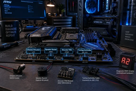
The larger issue is that motherboard manuals often expose the connector but do a poor job of telling buyers whether their particular board, chassis, or optional accessory can make use of it. XDA Developers examined an unspecified MSI B650M board and called out JCI1 chassis intrusion, JFP2 speaker/buzzer, JTPM1 discrete TPM, and JDASH1 tuning-controller connectors. MSI’s own manuals confirm that these labels and functions remain in use across recent AM5 and Intel desktop boards, although the headers are far from uniform between models.
The article’s most useful finding is not that these connectors exist. It is that a pin header printed on a motherboard is not a promise of a feature you can use. Before buying an accessory—or assuming a connector is dead weight—check the manual for the exact board revision and pinout.
JCI1 is a real tamper signal, but it is only as good as the chassis
JCI1 is a two-pin chassis-intrusion connector. With a compatible case switch attached and the feature enabled in UEFI firmware, opening the side panel changes the switch state and records or displays an intrusion warning on the next boot. MSI labels the connector JCI1, while other board makers may place the same function in the front-panel block or call it CI.
For a self-built gaming PC, the practical obstacle is the one XDA Developers identified: retail cases very rarely include the required cable and mechanical switch. A bare JCI1 header cannot detect an open panel on its own. It needs a physical switch mounted where a side panel depresses it, and the switch must be wired correctly for the board’s expected open or closed state.
That does not make chassis intrusion obsolete. Dell continues to document cover-removal alerts on OptiPlex desktops, including BIOS options to enable detection and clear an alert after authorized service. Lenovo’s current ThinkSystem documentation also treats an opened-chassis event as a serviceable hardware warning and directs administrators to inspect the intrusion switch and cable. In managed fleets, the signal can establish that physical access occurred—even if it cannot identify who opened the machine or stop a determined attacker from replacing hardware.
The limitation is important for Windows administrators. A chassis-open event is evidence of access, not protection against compromise. Someone who can open a desktop may be able to alter drives, install a malicious PCIe device, reset firmware settings, or remove components. HP has warned in its own guidance on open-chassis attacks that physical access exposes a broad attack surface, and that BIOS mitigations do not replace physical security controls.
A workstation handling sensitive data should therefore treat a chassis switch as one layer in a chain: locked room or cabinet, UEFI administrator password, Secure Boot, BitLocker, endpoint monitoring, and an incident process for unexpected physical-access alerts. On a personal tower, JCI1 is usually not worth retrofitting. In a lab, kiosk, branch-office deployment, or small server room, it can be a cheap and useful tamper indicator if the chassis supports it.
JFP2 still has a place when Windows never gets a chance to load
The JFP2 header is more relevant than it looks. MSI manuals still describe it as a connection for a buzzer or speaker, the small piezoelectric device once routinely supplied with PC cases. It emits POST—power-on self-test—beep codes before Windows, GPU drivers, or even a functional display output are available.
Modern boards commonly replace that speaker with diagnostic LEDs. MSI’s EZ Debug LEDs, for example, isolate broad boot stages such as CPU, DRAM, VGA, and boot-device initialization. Those indicators are convenient and clearer than memorizing old BIOS beep patterns. They are not, however, a universal replacement for a speaker.
A debug LED tells a builder which broad subsystem is preventing POST. A speaker may provide a firmware-specific code that narrows the failure further, particularly on systems without an onboard two-digit POST display. More importantly, neither assumes that a monitor works. That matters when diagnosing a new build with a bad graphics card, an unsupported processor BIOS, unstable memory settings, or a display connection problem.
The speaker header is also valuable in situations that look surprisingly ordinary: a PC rebuilt outside its case, a test bench, a headless firewall, a home server, or an office machine with no monitor attached. Cheap motherboard speakers are still sold, but builders should not connect one blindly. The four-pin JFP2 layout varies by manufacturer and board generation, and the manual determines which pins are speaker positive and negative rather than buzzer positive and negative.
The sensible advice is simple. If a board has no POST-code display and you troubleshoot systems regularly, keep a compatible piezo speaker in the toolkit. It takes almost no space and may turn a black-screen failure from guesswork into a firmware diagnosis. For a PC that is already stable and enclosed in a case, leaving JFP2 vacant has no downside.
JTPM1 is optional for most Ryzen owners, not redundant for every organization
The discrete TPM header is the connector most likely to be misunderstood because Windows 11 made “TPM 2.0” a familiar requirement. Microsoft requires TPM 2.0 for Windows 11 and says the capability may be provided in firmware. On compatible AMD platforms, the setting normally appears in UEFI as AMD fTPM; Intel systems commonly expose the equivalent capability as Platform Trust Technology, or PTT.
That is why most AM5 builders do not need to buy a module for JTPM1. If Windows Security or tpm.msc reports a ready TPM with specification version 2.0, Windows 11, BitLocker, Windows Hello, and other TPM-backed capabilities have what they require. Microsoft’s current support guidance specifically notes that many retail motherboards have TPM capability available but disabled in firmware.
Still, “firmware TPM” and “discrete TPM” are different designs with different administrative tradeoffs. A firmware implementation is rooted in the platform’s existing security processor and is convenient: no extra part, no header compatibility risk, and no cost. A discrete TPM is a separate module attached through a board-specific header. Some regulated environments and security policies prefer—or explicitly require—the separate hardware component, even where Windows itself does not.
The header also had a brief practical moment in 2022. AMD acknowledged intermittent stuttering on some Windows 10 and Windows 11 systems with fTPM enabled and said affected customers could use a compatible discrete TPM as a workaround while waiting for firmware updates based on AGESA 1.2.0.7 or newer. That history should not be used as a reason to disable fTPM on a current, maintained machine: AMD’s published remedy was a motherboard BIOS update, and disabling the TPM can affect Windows 11 eligibility and security features.
There is another trap: TPM modules are not interchangeable merely because the header has the same number of pins. TPM connector wiring is vendor- and sometimes generation-specific. A module bought for one ASUS, Gigabyte, MSI, ASRock, Dell, or Lenovo system may not work in another. Administrators who genuinely need a discrete TPM should source the supported module from the motherboard vendor’s compatibility documentation, then record its ownership and recovery-key implications before enabling BitLocker.
JDASH1 exposes MSI’s split between mainstream and extreme boards
JDASH1 is the clearest example of a connector that exists without giving every buyer access to the full feature implied by its name. MSI documents it as a Tuning Controller connection for an optional module that can provide a POST-code display, power and reset controls, Clear CMOS, overclock retry, and fail-safe boot functions on supported enthusiast boards.
On MSI’s high-end boards with the full 14-pin JDASH1 implementation, that controller makes sense for competitive overclocking and open-bench testing. A failed memory or CPU overclock can leave a system unable to boot normally; having physical controls and a code display near the board can save repeated case openings, jumper moves, and power cycles.
But MSI documentation for several mainstream boards shows a six-pin JDASH1 version with only the SMBus clock and data lines, 5V, ground, and two nonfunctional or keying positions. The extra control signals used by the full module are absent. XDA Developers was right to flag that discrepancy: a six-pin header may retain a family name shared with premium boards while lacking the connections required for the controller’s advanced buttons.
That is not accidental nostalgia. It is usually a consequence of shared platform design and documentation across product tiers. Reusing portions of a board design or firmware interface can cost less than redesigning every trace and manual section for a lower-tier SKU. But it produces a poor customer experience when a header’s presence suggests an upgrade path that the pinout does not actually provide.
For ordinary Windows users, JDASH1 can be ignored. For buyers choosing a board specifically for overclock recovery, bench testing, or hardware validation, it is a reminder to verify whether the board offers a two-digit debug display, onboard power/reset buttons, a clear-CMOS button, BIOS flashback, and the full accessory connector—not merely a familiar label in the manual.
The enduring lesson from these four headers is practical rather than nostalgic: motherboard connectors should be evaluated by the hardware and firmware around them. JCI1 needs a compatible chassis switch, JFP2 needs a small speaker, JTPM1 needs a vendor-supported module and a policy reason, and JDASH1 needs the right board-level pinout. For most desktop builds they will remain unused, but calling them purposeless misses the people who discover their value precisely when a PC has stopped behaving like a normal PC.
References
- I found four obscure motherboard headers that serve almost no purpose, but manufacturers keep shipping them anyway XDA · 2026-09-18T20:30:16+00:00